

While calipers are infinitely more accurate than a ruler, the final word in accuracy is the micrometer. By providing a smoother and finer movement along with a more ridged frame, micrometers take the guesswork out of the “in-between” measurements. Like precision calipers, micrometers come in a number of styles, but unlike calipers, you need a separate micrometer to measure outside, inside, and depth dimensions. For modeling, a 1” outside micrometer is ideal, Fig. 13.
Micrometers measure by using a finely threaded shaft that moves the spindle in and out when the barrel is rotated. Measurements are shown on scales engraved on the micrometer barrel and thimble. Although similar, learning to read a micrometer is easier than reading a vernier caliper.
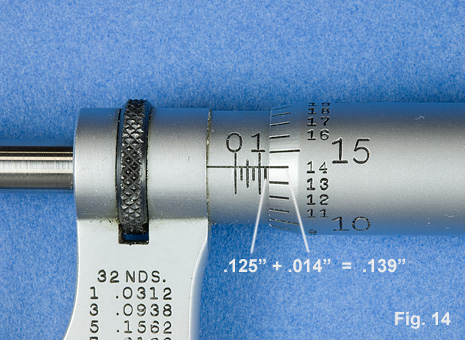
To read a micrometer you must take numbers from two different scales and add them together just as you did with the vernier caliper. The base number is taken from the scale on the barrel. On a typical micrometer that reads in thousandths (.001”) Fig. 14, each rotation of the thimble opens or closes the micrometer .025”. This is registered on the barrel, where each mark represents .025”. After noting the base number, look at the scale that is engraved around the thimble. Each mark represents .001” (one thousandth of an inch). You read the number on the barrel that lines up with the horizontal reference line on the base scale and add it to the base number. In the example, Fig. 14, your read .125” on the base scale and .014” on the thimble scale. The total is measurement is .139”.
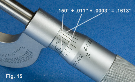
Some micrometers have an additional vernier on the barrel that will allow you to accurately measure to .0001”, Fig.15
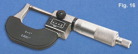
Like calipers, there are other types of micrometers that display their readings in a more direct way. Figure 16 shows a micrometer that uses a mechanical counter to register the measurement. This type helps minimize errors that may arise from inexperience, but for precision you need to verify the accuracy by reading the measurement from the conventional thimble and sleeve that is also provided with this type.
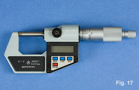
Again, like calipers, micrometers are also available in digital format, Fig. 17. This type operates much the same way as the digital calipers. And again, if possible, select one that has a manual on and off switch rather than an automatic "power-off feature". While these types of micrometers are easy to read and very accurate, I have found them to be bulky, heavy, and generally cumbersome to handle. Even more so than calipers, using a micrometer requires a certain "feel". It is extremely important to develop a sense of how much pressure to apply. Some Micrometers come equipped with a ratcheted thimble which can help keep pressure consistent. My experience has been that the comfort and handling of a standard one inch "mike" counts for more than the digital display. If you only own one micrometer, my personal recommendation would be to have a top quality one inch outside micrometer that reads in thousandths.

Most measuring devices, as well as stock building materials (tubing, sheet stock, etc.), utilize actual full size dimensions. As a scale modeler, you are constantly converting between these "real world numbers" and scale dimensions. Making these conversions becomes easier when there is a thorough understanding of how scale relates to prototype
What does it mean when a model is constructed in 1/48th scale? When a model is built in 1/48th scale it means that the model is 1/48th the size of the real subject, or that the real subject is 48 times larger than the model. In this example every 1/48th scale inch equals .021" in real measurements. You can easily check this by simply dividing 1" by 48. In the reverse, every one "real" inch is equal to 48 scale inches. These same principles apply to any scale. When converting between real and scale dimensions, you will find it makes the most sense to work in units of inches or decimal fractions of inches. As an example, you have a prototype dimension of 42' 8 3/4" and you want to know how long this is in 1/87th (HO) scale. The first step is to convert 42' 8 3/4" into decimal inches: 42' X 12 = 504", then add 504" + 8" = 602" ; next you need to convert 3/4" to a decimal by dividing 3 by 4 = .75" which you add to the 602" for a total of 602.75". Finally you divide 602.75 by 87 and get 6.928". Whether you are transforming prototype dimensions to scale dimensions or back again, the first step is to convert all your dimensions to decimal equivalents.
Sometimes scale is expressed as a certain unit equaling one foot and this can lead to confusion. Let's take the example of 1/48 scale. In this scale 1/4" is equal to one scale foot and you can often hear old craftsmen quickly referring to 1/48 scale as "quarter inch to the foot". On the other hand, RC modelers routinely use the term "quarter scale". To the uninitiated, these two expressions, "quarter inch to the foot" and "quarter scale", might seem to be referring to the same scale. However, nothing could be further from the truth. The term "quarter scale" actually does mean 1/4" is equal to one scale inch or that the model is 1/4 the size of the prototype.. "Quarter scale" is more properly termed "one forth scale". For ease in calculating individual measurements, it usually makes more sense to convert scales that are indicated as a fraction of an inch equaling one foot to a straight fractional scale. For example: 3/16" = 1' would be easier to use if expressed as 1/64 scale. To reach this answer multiply 12 x 16 = 192 (this is the conversion to inches), then divide 192 by 3 which equals 64.
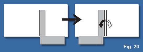
As well as distances, scale modelers need to know angles. An essential on any modelers workbench is a square. Squares are manufactured in different styles of fixed and adjustable types, Fig. 19. Because modelers work on small objects or in small spaces, you are not always able to use even the smallest of manufactured squares. I have also found it helpful to have a few homemade "squares" handy. These are also pictured in Fig. 19. These can be as simple as a small piece of acrylic or brass sheet with edges at 90 degrees. Squares are used to check angles of 90 degrees and in the case of adjustable squares, 45 degrees as well. While adjustable squares can be more versatile, good quality fixed squares are generally more accurate. Obviously, squares have to be precise, if a square isn't square then it's useless. To check a square for accuracy, place the square against a straight edge and draw a line; then turn the square over and draw another line right next to the first line, Fig. 20. If the lines are parallel, then the square is square; if the lines are not parallel, then get rid of it, repair it, or mark it as bad. I think it's a good idea to have several different sizes of fixed squares along with a good adjustable type
Although a square appears to be a very basic tool, you still need to know the proper technique for it's use, Fig. 21. The first step in checking squarness is to make sure that the object you are checking is firmly against the beam (bottom of the square). Slide the square so that the blade (vertical portion of square) just contacts the edge of the object. Now carefully check the space between the blade and the object. Is there a gap at the top or bottom? Is there no gap at all? When you use this method with the base of he object firmly against the beam of the square, you only need to look at the contact between the blade and the object. In the example of what not to do, the object is forced into the corner of the square which is not stable and could result in a gap against the beam, the blade, or both. This also happens if you push the object against the blade with too much force. Finally, always repeat your squarness checks several times; it never hurts to be sure.


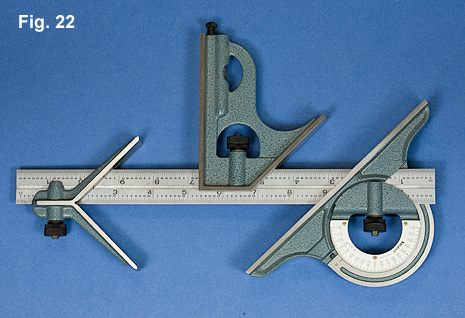
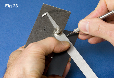
Protractors are adjustable devices used to indicate any degree of angle. Protractors are also available in several styles that are useful to modelers. Because protractors are subject to the same type of errors found with rulers, they should not be used in place of a square when checking for 90 degrees. However, you can get a pretty good idea of how accurate your protractor is if you check it for accuracy at the 90 degree setting. Simply loosen the protractor and hold it against a fixed square. If the indicated angle is not 90 degrees, you have a problem. Some protractors have a scale that can be adjusted so as to fine tune their readings. With other types, it may be necessary to modify the indicator mark on the movable arm. Figure 22 shows a combination square, protractor, and center square. Figure 23 demonstrates the use of an adjustable protractor for scribing a line at a specific angle. Protractors can be very cumbersome to use around a model. It is frequently easier to use the protractor to mark a piece of cardstock that can then be cut to the needed angle and will better fit the application.
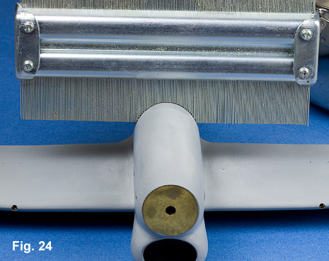
Another measuring device is a contour gauge, Fig. 24. This device uses a tightly packed row of steel pins to register contours. The registration of contours can be a bit course because of the size of the pins. Care should be taken to prevent the pins from getting bent and out of alignment.
With the exception of rulers, measuring tools are precision instruments. Exercise care in their handling, use, and storage. Don't leave them buried under all manner of "work-bench paraphernalia" where they can come in contact with glues, soldering flux, or worse. Take precautions to keep them away from abrasive particles such as sandpaper or a grinding stone debris. With care, good measuring instruments are a lifetime investment and a must for scale modeling.